 |
Measurements and data - Induced Polarization |
IntroductionThere are four techniques for observing chargeability: two using a charging current that is turned abruptly off so that discharging can be observed in the time domain, and two in which the dispersive nature (or effect as a function of frequency) of the phenomenon is observed in the frequency domain. Two types of time domain dataConsider the experiment illustrated in the following figure. Current is injected into the ground at the I source electrodes and voltage is measured at the V potential electrodes. The source is DC (direct current) in the sense that when it is on, there is no variation. However, in this case it is turned on and off with a duty cycle as shown in the figure. Two methods of measuring chargeability in the time domain are described below.
Two types of frequency domain dataAn oscillating source current can be employed to observe chargeability. The measurements are often still referred to as "DC resistivity" because the frequencies are relatively low. The resulting data will include (i) a "DC resistivity" based upon the voltages measured with the lowest source frequency, and (ii) a chargeability based upon the measurements explained next. Two methods of measuring chargeability in the frequency domain are described below.
If the voltage version is used, the Frequency Effect (FE) can easily be converted to a percent frequency effect by multiplying by 100.  Relating the four types of dataThe different IP responses all result from the build up of polarizing charges, but they do not produce the same numbers. In fact, the units of the various measurements are different. Nevertheless, the following approximate rule of thumb allows conversion between the different data sets:
Data acquisitionTime domain IPAs noted above, when time domain IP is recorded, chargeability M is measured as the area under the decay curve normalized by "primary" voltage VP, using Source (input) current is a square wave with 50% duty cycle (equal on and off times) as per resistivity (repeated cycles of +on, off, -on, off). The use of positive and negative cycles in transmitter current is very important for time-domain IP work. The correct area under the decay curve will be measured only if the potential decays exactly to zero. This will not occur when there is a superimposed spontaneous potential (SP), which is usually the case. If only one polarity was used, the inevitable SP could not be detected and removed. Recording both positive and negative cycles allows the "off-time" potential (i.e. voltages recorded when the transmitter is off) to be estimated, and any non-zero component removed.
Many instruments record measured voltage, Vp, just before the transmitter is turned off, and then again 10 times while voltages decay during the off times. The results can then provide a calculated chargeability and an estimated spontaneous potential. The adjacent figure illustrates each measured parameter. Note that if the transmitter is not on for a long enough time, Vp will be measured before the charging time is finished, resulting in a voltage that is smaller than the actual Vp. Other instruments use alternative time windows, and some newer instruments digitize the whole waveform, but the fundamental concepts are the same for all time domain systems. Frequency domain IPThe percent frequency effect was defined above as either
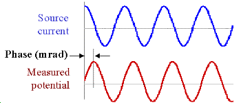
The low frequency can be measured using DC or very low frequency, and the second type of resistivities can be measured at frequencies on the order of a few tens to hundreds of Hertz. In practice, measurements are often made at two or more frequencies, and a PFE is calculated from the results. Phase IPWhen the phase of voltage with respect to input current is measured directly, the impedance of the ground can be determined based on the material. However, this requires careful synchronization between the receiver and the transmitter, and may be difficult on large surveys in rough country. Metal factorMetal factor is a parameter given by PFE or chargeability, M, divided by the corresponding apparent (i.e. measured) resistivity. Plots of this parameter emphasize where both low resistivity and high chargeability exist, or where there are significant occurrences of metallic mineralization (or graphite). However, metallic minerals (such as sulfides) are often disseminated, in which case the ore will more likely have high resistivity correlated with high M. For this and other reasons, the use of metal factor has declined and it is now rarely used. Choice of time, frequency or phase measurementsHere are a few factors affecting whether to choose time domain or freqeuncy domain survey types:
References
|